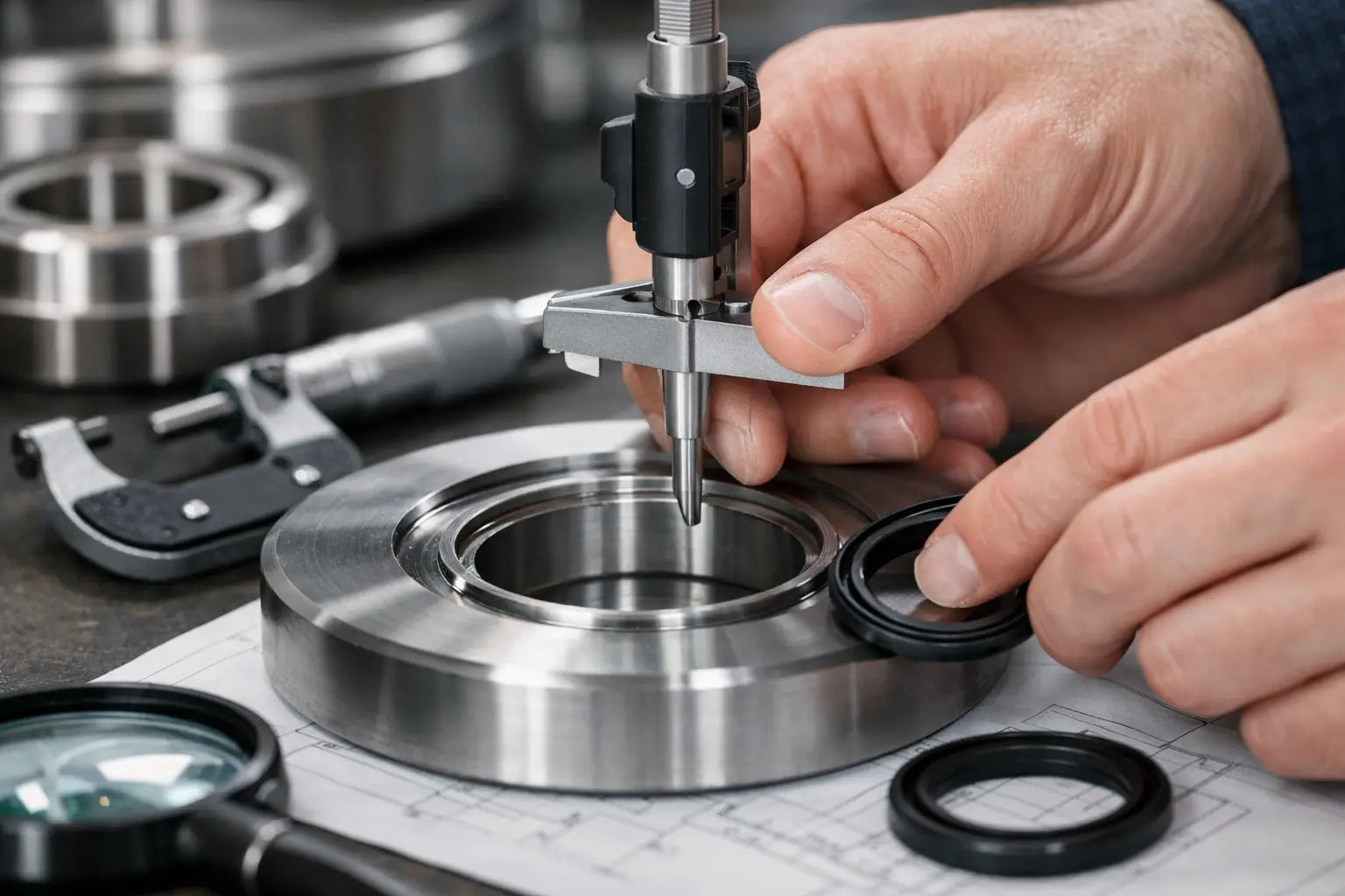
A replacement seal can look correct on the bench and still fail within hours if the groove dimensions are wrong. Knowing how to measure seal grooves lets you verify fitment before ordering a rod seal, piston seal, wiper, O-ring, backup ring, or complete hydraulic cylinder kit. For repair shops and fleet teams, that means fewer repeat teardowns, less oil loss, and less machine downtime.
Do not rely on the old seal alone. Heat, pressure, wear, and chemical exposure can change its size and shape. Measure the metal components, identify the seal profile, and record the dimensions in a format that can be matched against a seal catalog or OEM part number.
Start With the Correct Seal Location
Before taking measurements, identify where the seal sits and what it is required to do. A hydraulic cylinder commonly includes a rod wiper at the outer end of the gland, a rod seal to retain pressure, wear rings to guide moving parts, a piston seal, and sometimes static O-rings or backup rings between the gland and cylinder tube.
The groove location determines which dimensions matter. A rod seal groove is an internal groove in the cylinder gland. It seals around the rod. A piston seal groove is an external groove around the piston. It seals against the cylinder bore. A static O-ring groove may be on the gland outside diameter, at a threaded cap, or on a flange face.
Clean the part first. Remove oil, rust, adhesive residue, and fragments of the failed seal. A small piece of rubber trapped at the bottom of a groove can make the depth reading wrong enough to select the wrong cross section.
Tools for Measuring Seal Grooves
A digital caliper is suitable for many initial checks, especially when identifying a common excavator or loader seal kit. For final selection on critical hydraulic work, use a calibrated micrometer, telescoping gauge, bore gauge, or inside micrometer where appropriate. Depth gauges are useful for wide or deep grooves that cannot be measured accurately with caliper depth rods.
Use tools that fit the feature being measured. Caliper jaws can sit on a groove chamfer instead of the true groove edge. Telescoping gauges require a steady hand and should be checked with an outside micrometer after removal. For a worn cylinder, take readings in several positions rather than trusting a single point.
Record dimensions in both inches and millimeters if your equipment operates across mixed standards. Many heavy-equipment seal kits are specified in metric sizes, while repair tooling and older equipment records may use inch dimensions. Convert only after recording the original measurement.
How to Measure a Rod Seal Groove
A rod seal groove is inside the gland or cylinder head. The rod passes through its center, while the seal lip contacts the rod surface.
Start by measuring the rod diameter at an unworn area near the seal running surface. This is the seal inside diameter reference. Check for scoring, chrome damage, corrosion, or an out-of-round rod. A new seal cannot compensate for a damaged rod surface.
Next, measure the groove root diameter, also called the groove bottom diameter. This is the largest internal diameter inside the recessed groove. An inside micrometer or bore gauge gives the most dependable result. Measure the groove width between the two side walls, keeping the tool square to the groove.
For an internal rod seal groove, radial groove depth can be calculated as:
Radial depth = (groove root diameter - rod diameter) ÷ 2
Also inspect the lead-in chamfer at the gland entry. The seal must pass over this edge during installation without cutting or rolling the sealing lip. Record sharp edges, burrs, and excessive chamfer wear because they may need correction before reassembly.
How to Measure a Piston Seal Groove
A piston seal groove is machined around the outside diameter of the piston. Its sealing surface runs against the cylinder bore.
Measure the cylinder bore inside diameter in a clean, unworn section. Then measure the piston groove root diameter, which is the diameter at the bottom of the external groove. Measure the groove width across the side walls and inspect the corners for damage or rounded edges.
For an external piston groove, calculate radial groove depth as:
Radial depth = (cylinder bore diameter - groove root diameter) ÷ 2
Do not use a severely worn section of cylinder tube as the bore reference. A tube can bell-mouth near the gland end or wear in the central stroke area. Take bore readings at several depths and at 90-degree positions. If the tube is oversized, scratched, or out of round, replacing only the piston seal may not stop bypassing or restore holding performance.
Piston seal width is equally important. A seal that is too narrow can move excessively in the groove. One that is too wide may bind, distort, or prevent the piston from assembling into the tube. This is especially relevant for compact seals, step seals, and piston assemblies using separate wear rings.
Measure Groove Width, Corners, and Clearance
Diameter and groove width are the primary catalog dimensions, but they are not the whole job. Seal profiles have different requirements for groove corner radius, side-wall finish, and extrusion clearance.
Measure width at more than one point. Grooves can taper from machining wear, corrosion, or previous seal movement. Check that both walls are square and that there is no peening on the pressure side. A damaged wall can force the seal lip out of position under load.
For high-pressure applications, note the clearance gap between moving metal surfaces. On a rod seal, this is the gap between rod and gland. On a piston seal, it is the gap between piston and bore. Excessive clearance can extrude a standard elastomer seal, particularly when pressure spikes or oil temperature is high. A backup ring, anti-extrusion design, harder material, or a repair to the worn component may be required.
Surface condition matters as much as nominal size. Deep axial scratches on a rod, longitudinal scoring in a barrel, or sharp machining marks in a groove can shorten the life of a correctly sized seal. If the original failure shows a sliced lip, extrusion damage, hardening, or uneven wear, record that evidence before selecting the replacement.
Identify the Seal Profile Before Ordering
Two seals can share similar diameters and widths but have completely different profiles. A U-cup, compact rod seal, PTFE step seal, buffer seal, chevron packing, and double-lip wiper are not interchangeable just because they fit into a similar groove.
Examine the old seal and note its lip direction, material, energizer, fabric reinforcement, and whether it uses a separate O-ring or backup ring. Pressure seals are directional. Installing a U-cup or step seal backward can cause immediate leakage or pressure bypass.
When available, an OEM part number or cylinder kit number remains the fastest fitment check. Verify it against machine make, model, cylinder position, and application. A boom cylinder, arm cylinder, bucket cylinder, steering cylinder, tilt cylinder, and lift cylinder on the same machine may use different rod and piston dimensions.
If no part number is available, provide the measured rod or bore size, groove root diameter, groove width, seal profile, and machine application. A clear photo beside a caliper can help confirm unusual profiles, but it should support measured dimensions rather than replace them.
Avoid the Most Common Measurement Errors
The most costly mistake is measuring the removed seal and ordering the same apparent size. Seals are designed with interference, preload, and lip geometry. Their free-state dimensions do not necessarily equal groove dimensions or running diameters.
Another common error is measuring over a chamfer, plating damage, or a worn rod section. Take each reading twice, rotate the part where possible, and compare results. If measurements vary, document the smallest and largest readings. The variation may point to a component problem rather than a seal-selection problem.
Do not round dimensions too aggressively. A reading of 49.6 mm is not automatically a 50 mm groove. Compare the full set of dimensions with the available seal design and tolerance range. For a critical cylinder, confirm the dimensions against the equipment parts manual or the existing OEM kit reference before placing an urgent order.
Record Dimensions for Faster Future Repairs
A simple cylinder measurement record saves time on the next failure. Include machine model and serial range, cylinder position, rod diameter, bore diameter, each groove root diameter and width, seal profile, material, and any OEM or aftermarket part number. Add notes on rod condition, tube condition, and backup-ring use.
For fleets with repeated equipment models, this record turns a breakdown into a repeatable procurement job instead of a fresh identification exercise. It also makes it easier to stock the right BOOM KIT, BUCKET KIT, rod seal, piston seal, and wiper before a machine is down.
Accurate groove measurements give you a reliable starting point, but the finished repair still depends on clean components, correct seal orientation, proper installation tools, and inspection of the rod and cylinder bore. Measure the metal, match the profile, and order from verified dimensions so the replacement part is ready to work when the machine returns to service.